Description
Overview:
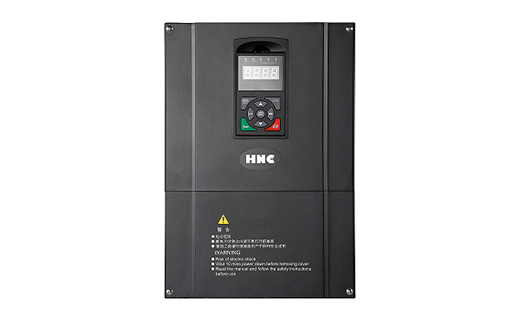
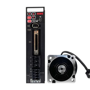
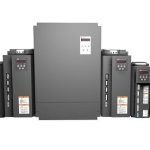
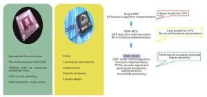
HSD2000 has perfect performance thanks to 64bit DSP, high performance FPGA, and the newest motor control algorithm. It could drive synchronous servo motor and asynchronous servo motor, as well as induction motors. Available for pulse / analog / field bus / digital input signal / keyboard control, and supports all types of encoders including incremental, SinCos, absolute, The power range is from 2.2KW up to 132KW.
Features:
1. Employed DSP+FPGA, reliability and performance is improved markedly High performance/ High flexibility / Strong over-load ability
2. Perfectly work as AC synchronous servo drive and asynchronous servo drive, can drive: synchronous servo motor (position control), asynchronous servo motor and induction motors.
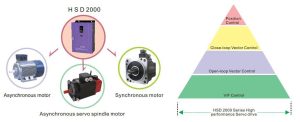
3. Speed mode/ torque mode/ servo mode/spindle drive mode optional
A. Speed mode
Open loop:For most of applications, like Cranes, CNC spindle
Close loop: For the applications require higher speed accuracy, e.g elevator, harbor cranes:
B. Torque mode:
Open loop:General winding applications, e.g leather winding, film winding
Close loop: Winding applications requires high tension accuracy, with winding diameter calculation, e.g steel panel winding.
C. Servo mode:
Pulse tracking: Usually co-work with CNC controller or other upper computer
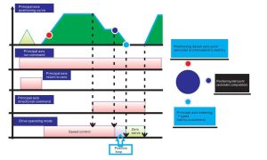
Positioning: CNC spindle positioning, internal digital positioning.
D. Spindle mode.
4. Auto-turning of synchronous servo motor pole angle, no need zeroing, match all brands of servo motor easily
5. Easy operation: pulse control / filed bus control / IO control / analog control
6. Under servo mode, positioning accuracy is less than ±1 pulse
7. Close-loop vector control, speed ratio is up to 1:5000,can achieve high speed accuracy
8. Time-sharing control of 2 motors with different parameters
Parameters:
| Item | Item description | |
| Input | Rated voltage; frequency | Three-phase, 380V~480V; 50Hz/60Hz; voltage unbalance rate: <3%; frequency: ±5% |
| Output | Rated frequency | 380V, 400V, 415V, 440V, 460V, 480V |
| Frequency | 0Hz~1000Hz | |
| Overload | G: 150% rated current in 2 minutes,200% rated current 0.5 seconds | |
| Main control performance | Control | magnetic flux vector control without PG, magnetic flux vector control with PG, servo control, V/F control, V/F control wit PG |
| Modulation method | Space vector PWM modulation method | |
| Speed range | 1: 200 (magnetic flux vector control without PG), 1: 5000 (magnetic flux vector control with PG, servo control) | |
| Start torque | 0Hz of 150% rated torque (magnetic flux vector control without PG), 0Hz of 200% rated torque (magnetic flux vector control with PG) | |
| Operational rotational speed steady-status accuracy | ≤±0.2% rated synchronous rotational speed (magnetic flux vector control without PG),
≤±0.02% rated synchronous rotational speed (magnetic flux vector control with PG, servo control) |
|
| Speed fluctuations | ≤±0.3% rated synchronous rotational speed (magnetic flux vector control without PG)
≤±0.1% rated synchronous rotational speed (magnetic flux vector control with PG、servo control) |
|
| Positioning accuracy | ±1 pulse | |
| Torque response | ≤10ms (magnetic flux vector control with PG, servo control);
≤20ms (magnetic flux vector control without PG) |
|
| Torque control | Support magnetic flux vector control without PG, magnetic flux vector control with PG, servo control | |
| Frequency accuracy | Digital setting: maximum frequency×±0.01%; analog setting: maximum frequency×±0.2% | |
| Frequency resolution | digital setting: 0.01Hz; analog setting: maximum frequency×0.05% | |
| Torque lifting | Automatic torque lifting, manual torque lifting 0.1%~30.0% | |
| V/F curve | Four types: one user setting V/F curve and 3 reduced torque curves (2.0 times the power, 1.7 times the power, 1.2 times the power) | |
| Acceleration and deceleration curves | Two types: straight acceleration and deceleration, S curve acceleration and deceleration; time of the four types: Time units (minutes / seconds) optional, maximum to 60 hours | |
| DC braking | Halt DC brake starting frequency: 0.00 Hz~60.00Hz; braking time: 0.0s~30.0s; brake current: 0.0%~100.0% | |
| Automatic Voltage Regulation (AVR) | When grid voltage changes, the output voltage keeps constant automatically. | |
| Automatic current limiting | Limit current in operation automatically to prevent over current failure tripping frequently. | |
| Automatic carrier wave adjustment | According to loading characteristics, the carrier wave frequency may be adjusted automatically; optional | |
| Customization capabilities | Textile swing frequency | Textile swing frequency control, achieve adjustable swing frequency function of center frequency |
| Binding function | Free banding and synchronous switching may be implemented between command channel and given frequency channel. | |
| Inching | Inching frequency range: 0.00Hz~50.00Hz; inching acceleration and deceleration time 0.1s~60.0s may best; inching interval may be se | |
| Multi-speed operation | Multi-speed operation will be achieved by inside PLC or control terminals. | |
| built-in process closed loop control | Form closed loop control system | |
| Operation function | Operation command channel | Given operation panel, control terminal and may be switched by varity of methods. |
| Given frequency channel | Given digital, analog voltage, analog current, pulse, serial port may be switched by variety of methods. | |
| Given auxiliary frequency | Achieve flexible auxilary frequency fine tuning, frequency synthesis | |
| Pulse output terminal | 0~100kHz pulse square wave signal output, achieve output of setting frequency, output frequency. | |
| Analog output terminal | 2analog signals output, 0/4~20mA or 0/2~10V may be selected separately. Achieve output of setting frequency, output frequency. | |
| operation panel | LED display | Display 20 types of parameters such as setting frequency, output frequency, output voltage and output current . |
| LCD display | Optional, Chinese / English prompts content | |
| Parameter copy | Operation panel may be used to achieve rapid copy of parameters | |
| Key lock and function selection | Achieve parts or all locking functions pf keys. Define function range of part key to prevent error operation. | |
| Protective function | lack-phase protection (optional) , over current protection, overvoltage protection, lack-voltage protection, over-thermal protection, overload protection, off-load protection | |
| Environment | Condition | Indoor, without sunlight, dust, corrosive gases, flammable gas, mist, water vapor, dripping or salt. |
| Altitude height | Derating above 1000 meters, derating 10% in each 1000 meters lifting | |
| Ambient temperature | -10℃~+40℃ (ambient temperature between 40℃~50℃, derating ) | |
| Environment | Humidity | 5%~95%RH, without condensing |
| Vibration | Less than 5.9m/s2 (0.6g) | |
| Storage temperature | -40℃~+70℃ | |
| Structure | Protective degree | IP20 |
| Cooling method | Air-cooled with fan control | |
| Servo Drive Model | Rated Capacity (kVA) | Rated Input Current (A) | Rated Output Current (A) | Adaptive Motor (kW) |
| HSD2000-4T-1R5 | 3 | 5 | 3.7 | 1.5 |
| HSD2000-4T-2R2 | 4 | 5.8 | 5 | 2.2 |
| HSD2000-4T-004 | 6.3 | 10 | 9 | 4 |
| HSD2000-4T-5R5 | 8.5 | 15.5 | 13 | 5.5 |
| HSD2000-4T-7R5 | 11 | 20.5 | 17 | 7.5 |
| HSD2000-4T-011 | 17 | 26 | 25 | 11 |
| HSD2000-4T-015 | 21 | 35 | 32 | 15 |
| HSD2000-4T-018 | 24 | 38.5 | 37 | 18.5 |
| HSD2000-4T-022 | 30 | 46.5 | 45 | 22 |
| HSD2000-4T-030 | 40 | 62 | 60 | 30 |
| HSD2000-4T-037 | 50 | 76 | 75 | 37 |
| HSD2000-4T-045 | 60 | 92 | 90 | 45 |
| HSD2000-4T-055 | 72 | 113 | 110 | 55 |
| HSD2000-4T-075 | 100 | 157 | 152 | 75 |
| HSD2000-4T-090 | 116 | 180 | 176 | 90 |
| HSD2000-4T-110 | 138 | 214 | 210 | 110 |
| HSD2000-4T-132 | 167 | 256 | 253 | 132 |
| HSD2000-4T-160 | 200 | 307 | 304 | 160 |
| HSD2000-4T-185 | 230 | 355 | 350 | 185 |
| HSD2000-4T-200 | 250 | 385 | 380 | 200 |
| HSD2000-4T-220 | 280 | 430 | 426 | 220 |
| HSD2000-4T-250 | 309 | 488 | 470 | 250 |
| HSD2000-4T-280 | 342 | 525 | 520 | 280 |
| HSD2000-4T-315 | 388 | 605 | 590 | 315 |
| HSD2000-4T-355 | 427 | 667 | 650 | 355 |
| HSD2000-4T-400 | 454 | 701 | 690 | 400 |
| HSD2000-4T-450 | 510 | 789 | 775 | 450 |
| HSD2000-4T-500 | 566 | 877 | 860 | 500 |
| HSD2000-4T-560 | 625 | 982 | 950 | 560 |
| HSD2000-4T-630 | 724 | 1184 | 1100 | 630 |
| HSD2000-4T-800 | 921 | 1500 | 1400 | 800 |
Dimension:
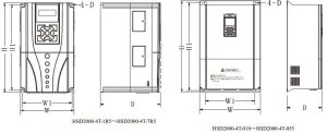
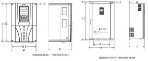
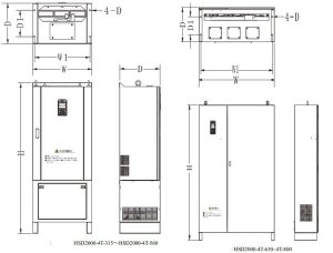
| Servo drive model | D | W1 | H1 | H | W | Outline Drawing No. | Installation hole diameter | Gross weight (kg) | Installation method |
| HSD2000-4T-1R5 | 175 | 127 | 200 | 215 | 140 | Figure2-3 | 5 | 3.5 | Hanging |
| HSD2000-4T-2R2 | |||||||||
| HSD2000-4T-004 | |||||||||
| HSD2000-4T-5R5 | 181 | 146 | 251 | 262 | 157 | Figure2-3 | 5.5 | 5 | Hanging |
| HSD2000-4T-7R5 | |||||||||
| HSD2000-4T-011 | 181 | 180 | 288 | 305 | 198 | Figure2-4 | 5.5 | 8 | Hanging |
| HSD2000-4T-015 | |||||||||
| HSD2000-4T-018 | 220 | 230 | 424.5 | 438 | 276 | Figure2-5 | 7 | 18 | Hanging |
| HSD2000-4T-022 | |||||||||
| HSD2000-4T-030 | |||||||||
| HSD2000-4T-037 | 231.5 | 320 | 571 | 589 | 395 | Figure2-5 | 10 | 45 | Hanging |
| HSD2000-4T-045 | |||||||||
| HSD2000-4T-055 | |||||||||
| HSD2000-4T-075 | 298 | 320 | 733 | 759 | 489 | Figure2-6 | 12 | 75 | Hanging |
| HSD2000-4T-090 | |||||||||
| HSD2000-4T-110 | |||||||||
| HSD2000-4T-132 | 370 | 320 | 898 | 927 | 539 | Figure2-6 | 12 | 125 | Hanging and cabinet |
| HSD2000-4T-160 | |||||||||
| HSD2000-4T-185 | 507 | 898 | 1377 | 539 | Figure2-6 | 142 | |||
| HSD2000-4T-200 | |||||||||
| HSD2000-4T-220 | 373 | 280 | 1022 | 1054 | 704 | Figure2-6 | 12 | 160 | Hanging and cabinet |
| HSD2000-4T-250 | 672 | 1022 | 1500 | 704 | Figure2-6 | 181 | |||
| HSD2000-4T-280 |


