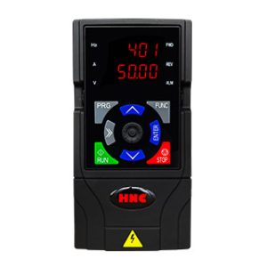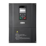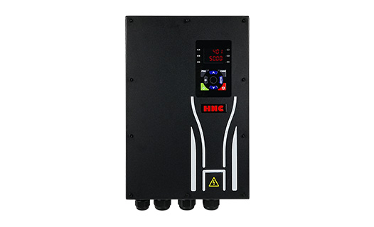
Description
HV100W series is a general current vector control inverter integrated with the performance and features in a high degree, and high protection level (IP65). HV100W with industry-leading drive performance and functionality control, using unique current vect
Overview:
HV100W series is a general current vector control inverter integrated with the performance and features in a high degree, and high protection level (IP65). HV100W with industry-leading drive performance and functionality control, using unique current vector control algorithm can efficiently drive induction motor to achieve high accuracy, high torque and high-performance control.
Exquisite appearance design, reliable hardware structure,dual display, independent air duct, powerful functions, rich macro parameters .ect. These optimized designs make HV100W series an industry-leading product and bring tangible benefits to customers.
Customer success, Market Service!
HV100W in terms of performance and control are worthy of trust!
Features:
- Advanced motor control technology support Open loop vector control(SVC) and V/F control.
- High protection level (IP65) is designed for unprotected use in all outdoor and bad environments.
- Double-line digital display, can display more content
- Powerful macro function, one-key setting, saving customer debugging time
- Different input voltage(220V single phase/220V 3 phase/380V 3 phase/460V 3 phase).
- High starting torque characteristics and precise speed control.
- Upgrade I/O(NPN/PNP compatible) can meet more application requirement.
- Programmable DI/DO/AI/AO, and Modbus RTU make easy communication with other devices.
- Independent air duct design prevents dust from contacting the circuit board, better heat dissipation performance.
Parameters:
Model Definition:
| Model | Input current (A) | Output current (A) | Adaptive motor
(KW) (HP) |
|
| G1 input voltage range: Single-phase AC220V±15%, 50 / 60 Hz | ||||
| HV100W-R75G1 | 8.2 | 4.5 | 0.75 | 1 |
| HV100W-1R5G1 | 14 | 7 | 1.5 | 2 |
| HV100W-2R2G1 | 23 | 10 | 2.2 | 3 |
| G2 input voltage range: Three-phase AC220V±15%, 50 / 60 Hz | ||||
| HV100W-R75G2 | 5 | 4.5 | 0.75 | 1 |
| HV100W-1R5G2 | 7.8 | 7 | 1.5 | 2 |
| HV100W-2R2G2 | 10.5 | 10 | 2.2 | 3 |
| HV100W-004G2 | 16.6 | 16 | 3.7 | 5 |
| HV100W-5R5G2 | 26 | 20 | 5.5 | 7.5 |
| HV100W-7R5G2 | 35 | 30 | 7.5 | 10 |
| HV100W-011G2 | 46.5 | 42 | 11 | 15 |
| HV100W-015G2 | 62 | 55 | 15 | 20 |
| HV100W-018G2 | 75 | 70 | 18.5 | 25 |
| HV100W-022G2 | 85 | 80 | 22 | 30 |
| HV100W-030G2 | 115 | 110 | 30 | 40 |
| HV100W-037G2 | 135 | 130 | 37 | 50 |
| HV100W-045G2 | 165 | 160 | 45 | 60 |
| HV100W-055G2 | 210 | 200 | 55 | 75 |
| G3 input voltage range: Three-phase AC 380~440 (-15%~+10%), 50 / 60 Hz | ||||
| HV100W-R75G3 | 3.4 | 2.5 | 0.75 | 1 |
| HV100W-1R5G3 | 5 | 3.7 | 1.5 | 2 |
| HV100W-2R2G3 | 5.8 | 5 | 2.2 | 3 |
| HV100W-004G3 | 10.5 | 9 | 4.0 | 5 |
| HV100W-5R5G3 | 14.6 | 13 | 5.5 | 7.5 |
| HV100W-7R5G3 | 20.5 | 17 | 7.5 | 10 |
| HV100W-011G3 | 26 | 25 | 11 | 15 |
| HV100W-015G3 | 35 | 32 | 15 | 20 |
| HV100W-018G3 | 38.5 | 37 | 18.5 | 25 |
| HV100W-022G3 | 46.5 | 45 | 22 | 30 |
| HV100W-030G3 | 62 | 60 | 30 | 40 |
| HV100W-037G3 | 80 | 75 | 37 | 50 |
| HV100W-045G3 | 94 | 90 | 45 | 60 |
| HV100W-055G3 | 128 | 110 | 55 | 75 |
| HV100W-075G3 | 160 | 150 | 75 | 100 |
| HV100W-093G3 | 190 | 176 | 93 | 125 |
| HV100W-110G3 | 225 | 210 | 110 | 150 |
| G4 input voltage range: Three-phase AC 460~480 (-15%~+10%), 50 / 60 Hz | ||||
| HV100W-R75G4 | 3.4 | 2.5 | 0.75 | 1 |
| HV100W-1R5G4 | 5 | 3.7 | 1.5 | 2 |
| HV100W-2R2G4 | 5.8 | 5 | 2.2 | 3 |
| HV100W-004G4 | 10.5 | 9 | 4.0 | 5 |
| HV100W-5R5G4 | 14.6 | 13 | 5.5 | 7.5 |
| HV100W-7R5G4 | 20.5 | 17 | 7.5 | 10 |
| HV100W-011G4 | 26 | 25 | 11 | 15 |
| HV100W-015G4 | 35 | 32 | 15 | 20 |
| HV100W-018G4 | 38.5 | 37 | 18.5 | 25 |
| HV100W-022G4 | 46.5 | 45 | 22 | 30 |
| HV100W-030G4 | 62 | 60 | 30 | 40 |
| HV100W-037G4 | 80 | 75 | 37 | 50 |
| HV100W-045G4 | 94 | 90 | 45 | 60 |
| HV100W-055G4 | 128 | 110 | 55 | 75 |
| HV100W-075G4 | 160 | 150 | 75 | 100 |
| HV100W-093G4 | 190 | 176 | 93 | 125 |
| HV100W-110G4 | 225 | 210 | 110 | 150 |
Standard specifications:
| Input | Rating Voltage ,
Frequency |
Three-phase (G3/G4 series) 380V-480V, 50/60HZ
Single&Three-phase (G1/G2 series) 220 V: 50/60 Hz |
|||
| Allowable range
of voltage |
Three-phase (G3 series) : AC 380~440 (-15%~+10%)
Three-phase (G4 series) : AC 460~480 (-15%~+10%) Single&Three-phase (G1/G2 series) : AC220V±15% |
||||
| Output | Voltage | G1/G2 series; 0~220V, G3 series; 0~440 V, G4 series; 0~480 V | |||
| Frequency | Low frequency mode: 0 ~ 300 Hz; high frequency mode: 0 ~ 3000 Hz | ||||
| Overload capacity | G type machine: 110% long-term; 150% 1 minute ;200% 4 seconds
P type machine: 105% long-term ;120% 1 minute; 150% 1 second |
||||
| Control mode | V/F control, advanced V/F control, V/F separation control and PG-free current vector control | ||||
| Control characteristic | Frequency setting
Resolution |
Analog end input | 0.1% of the maximum output frequency | ||
| Digital settings | 0.01Hz | ||||
| Frequency accuracy | Analog input | Within 0.2% of the maximum output frequency | |||
| Digital input | Set the output frequency within 0.01% | ||||
| V/F control | V/F curve (voltage frequency characteristic) | The reference frequency can be set arbitrarily from 0.5 Hz to 3000 Hz, and the multi-point V/F curve can be set arbitrarily. You can also choose a variety of fixed curves such as constant torque, torque reduction 1, torque reduction 2 and square torque | |||
| Torque boost | Manual setting: 0.0 ~ 30.0% of rated output
Automatic boost: automatically determine the boost torque according to the output current and motor parameters |
||||
| Automatic current and voltage limiting | Whether in acceleration, deceleration or stable operation, the motor stator current and voltage can be automatically detected, which can be suppressed within the allowable range according to the unique algorithm to minimize the possibility of system fault tripping | ||||
| Control characteristic | Sensorless vector control | voltage frequency characteristic | Automatically adjust output voltage-frequency ratio according to motor parameters and unique algorithm | ||
| Torque characteristic | Starting torque:
150% rated torque at 3.0Hz (VF control) 150% rated torque at 1.0Hz (advanced VF control) 150% rated torque at 0.5Hz (without PG current vector control) Running speed steady-state accuracy: ≤± 0.2% rated synchronous speed Speed fluctuation: ≤± 0.5% rated synchronous speed Torque response: ≤20ms (without PG current vector control) |
||||
| Self-determination of motor parameters | Without any restriction, the parameters can be automatically detected under static and dynamic conditions to obtain the best control effect | ||||
| Current and voltage suppression | Full-range current closed-loop control, completely avoiding current impact, with perfect overcurrent and overvoltage suppression function | ||||
| Running
undervoltage suppression |
Especially for users with low grid voltage and frequent fluctuation of grid voltage, the system can maintain the longest possible operation time according to the unique algorithm and residual energy allocation strategy even in the range below the allowable voltage | ||||
| Typical function | Multi speed and
Swing frequency operation |
16-stage programmable multi-stage speed control and multiple operation modes are optional. Swing frequency operation: preset frequency and center frequency can be adjusted, and state memory and recovery after power failure | |||
| PID control
RS485 communication |
Built-in PID controller (preset frequency). Standard configuration RS485 communication function, multiple communication protocols can be selected, with linkage synchronous control function | ||||
| Frequency setting | Analog input | DC voltage 0 ~ 10 V, DC current 0 ~ 20 mA (upper and lower limits are optional) | |||
| Digital input | keypad setting, RS485 interface setting, UP/DOWN terminal control, and various combination settings with analog input can also be made. | ||||
| Output signal | Digital output | 2 Y-terminal open collector outputs and two programmable relay outputs (TA/TB/TC), with up to 61 functions | |||
| Analog output | 2 analog signals are output, and the output range can be flexibly set between 0 ~ 20mA or 0 ~ 10V, which can realize the output of physical quantities such as set frequency and output frequency | ||||
| Automatic voltage stabilizing operation | According to the needs, three modes can be selected: dynamic voltage stabilization, static voltage stabilization and non-voltage stabilization, so as to obtain the most stable operation effect | ||||
| Acceleration and deceleration
Time setting |
0.1s~3600.0min can be set continuously, and S-type and linear mode can be selected | ||||
| Brake | Energy
consumption Brake |
Energy consumption braking starting voltage, return difference voltage and energy consumption braking rate can be continuously adjusted | |||
| Direct current
Brake |
Starting frequency of DC braking during shutdown: 0.00 ~ [000.13] upper limit frequency
Braking time: 0.0 ~ 100.0 s; Braking current: 0.0% ~ 150.0% rated current |
||||
| Magnetic flow
Brake |
0 ~ 100 0: invalid | ||||
| Low noise operation | The carrier frequency is continuously adjustable from 1.0 kHz to 16.0 kHz to minimize the noise of the motor | ||||
| Revolving speed tracking speed
Restart facility |
It can realize the smooth restart and instantaneous stop restart of the motor in operation | ||||
| Counter | One internal counter is convenient for system integration | ||||
| Operating function | Upper and lower limit frequency setting, frequency jump operation, reverse operation limit, slip frequency compensation, RS485 communication, frequency increment and decrement control, fault self-recovery operation, etc | ||||
| Display | keypad display | Running
State |
Output frequency, output current, output voltage, motor speed, set frequency, module temperature, PID setting, feedback amount, analog input and output, etc |
| Alarm
Content |
The last six fault records, the record of six operation parameters such as output frequency, set frequency, output current, output voltage, DC voltage and module temperature during the last fault trip. | ||
| Protection function | Over-current, over-voltage, under-voltage, module failure, electronic thermal relay, overheating, short circuit, input and output phase failure, abnormal tuning of motor parameters, internal memory failure, etc. | ||
| Environment | Ambient temperature | -10℃ ~+40℃ (the ambient temperature is 40℃ ~ 50℃, please use it at a reduced level) | |
| Ambient humidity | 5% ~ 95% RH, no water condensation | ||
| Surrounding environment | Indoor (no direct sunlight, corrosion, flammable gas, oil mist, dust, etc.) | ||
| Altitude | 1000 meters above the use of derating, every 1000 meters up derating 10% | ||
| Structure | Protection grade | IP65 | |
| Cooling mode | Air-cooled with fan control | ||
| Installation method | Wall mounted, cabinet mounted | ||
Dimension:
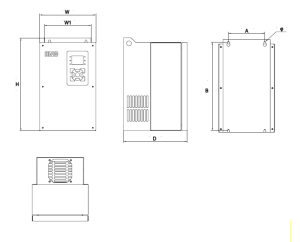
| Model | A
(mm) |
B
(mm) |
H
(mm) |
W
(mm) |
W1
(mm) |
D
(mm) |
Install Hole
(mm) |
| Installation | Exterior | ||||||
| HV100W-R75G1/2 | 80 | 240 | 250 | 140 | 110 | 190 | 5 |
| HV100W-1R5G1/2 | |||||||
| HV100W-2R2G1/2 | |||||||
| HV100W-R75G3/G4 | |||||||
| HV100W-1R5G3/G4 | |||||||
| HV100W-2R2G3/G4 | |||||||
| HV100W-004G3/G4 | |||||||
| HV100W-004G2 | 120 | 290 | 305 | 185 | 155 | 210 | 6 |
| HV100W-5R5G2 | |||||||
| HV100W-5R5G3/G4 | |||||||
| HV100W-7R5G3/G4 | |||||||
| HV100W-011G3/G4 | |||||||
| HV100W-7R5G2 | 160 | 360 | 375 | 240 | 210 | 200 | 7 |
| HV100W-011G2 | |||||||
| HV100W-015G2 | |||||||
| HV100W-015G3/G4 | |||||||
| HV100W-018G3/G4 | |||||||
| HV100W-022G3/G4 | |||||||
| HV100W-030G3/G4 | |||||||
| HV100W-018G2 | 200 | 482 | 500 | 300 | 270 | 230 | 7 |
| HV100W-022G2 | |||||||
| HV100W-037G3/G4 | |||||||
| HV100W-045G3/G4 | |||||||
| HV100W-030G2 | 245 | 520 | 540 | 345 | 315 | 290 | 9 |
| HV100W-037G2 | |||||||
| HV100W-055G3/G4 | |||||||
| HV100W-075G3/G4 | |||||||
| HV100W-045G2 | 270 | 555 | 575 | 380 | 350 | 320 | 9 |
| HV100W-055G2 | |||||||
| HV100W-093G3/G4 | |||||||
| HV100W-110G3/G4 | |||||||
Download:
| Series | Model | Download |
| Frequency Inverter | HV100W Series Frequency Inverter User Manual-V7.3 | |
| Frequency Inverter | HV100&HV100W Series Frequency Inverter Catalog-V2.0 |