Description
Overview:
HV580L series frequency inverter is the professional for elevator of HNC. It concludes below improvement & innovation based on the ordinary V/F inverter. With the high-end design and high quality and reliability, HV580 series inverter will bring the users all new experience.
-
1. Smooth ride performance
-
2. Integrated brake control
-
3. Default factory setting user friendly factory, get you started quickly.
-
4. 4-Indepenent S-Ramps
-
5. Programmable DC –injection braking
-
6. Complete functions for elevator application

Features:
HV580L series elevator inverter has Perfect performance:
1. Simplified parameter for easy start up
2. Comprehensive trip diagnostics
3. High start torque 180%/0Hz at FVC
4. Automatic torque boost
5. Slip compensation
6. Flexible programmable I/O connection
7. Output frequency 0~300Hz
8. In-built dynamic braking unit
9. To protect the mechanical torque limitation
10. High starting torque feature.
11. Superior responsiveness
12. Motor overheating protection
13. Prompt current limit function
Parameters:
| Variable frequency Drive type | Voltage V | Input Current A | Output current A | Adapter motor
Kw HP |
|
| HV580L-004G3 | 380V,50/60Hz | 10.5 | 8.5 | 4 | 5 |
| HV580L-5R5G3 | 380V,50/60Hz | 15.5 | 13 | 5.5 | 7.5 |
| HV580L-7R5G3 | 380V,50/60Hz | 21 | 16 | 7.5 | 10 |
| HV580L-009G3 | 380V,50/60Hz | 21 | 16 | 7.5 | 10 |
| HV580L-011G3 | 380V,50/60Hz | 27.6 | 25 | 11 | 15 |
| HV580L-015G3 | 380V,50/60Hz | 37.1 | 32 | 15 | 20 |
| HV580L-018G3 | 380V,50/60Hz | 41.9 | 38 | 18.5 | 25 |
| Item | Specifications | ||
| Standard
functions
|
Maximum frequency | • Vector control: 0–300 Hz• V/F control: 0–320 Hz | |
| Carrier
Frequency |
0.5–16 kHz
The carrier frequency is automatically adjusted based on the load features. |
||
| Input frequency
Resolution |
Digital setting: 0.01 Hz
Analog setting: maximum frequency x 0.025% |
||
| Control mode | • Sensorless flux vector control (SFVC)
• Closed-loop vector control (CLVC) • Voltage/Frequency (V/F) control |
||
| Startup torque | • G type: 0.5 Hz/150% (SFVC); 0 Hz/180% (CLVC)
• P type: 0.5 Hz/100% |
||
| Speed range | 1:100 (SVC) | 1:1000 (FVC) | |
| Speed stability
Accuracy |
±0.5% (SVC) | ±0.02% (FVC) | |
| Torque control
Accuracy |
±5% (FVC) | ||
| Overload capacity | • G type: 60sor 150% of the rated current, 3s for 180% of the rated current
• P type: 60s for 120% of the rated current, 3s for 150% of the rated current |
||
| Torque boost | • Fixed boost• Customized boost 0.1%–30.0% | ||
| V/F curve | • Straight-line V/F curve• Multi-point V/F curve
• N-power V/F curve (1.2-power, 1.4-power, 1.6-power,1.8-power,square) |
||
| V/F separation | Two types: complete separation; half separation | ||
| Ramp mode | • Straight-line ramp• S-curve ramp
Four groups of acceleration/deceleration time with the range of 0.0–6500.0s |
||
| DC braking | DC braking frequency: 0.00 Hz to maximum frequency
Braking time: 0.0–36.0s Braking action current value: 0.0%–100.0% |
||
| JOG control | JOG frequency range: 0.00–50.00 Hz
JOG acceleration/deceleration time: 0.0–6500.0s |
||
| Onboard multiple preset speeds | It implements up to 16 speeds via the simple PLC function or combination of X terminal states. | ||
| Onboard PID | It realizes process-controlled closed loop control system easily. | ||
| Auto voltage
regulation (AVR) |
It can keep constant output voltage automatically when the mains voltage changes. | ||
| Over voltage/
Over current stall Control |
The current and voltage are limited automatically during the running process so as to avoid frequent tripping due to over voltage/over current. | ||
| Fast current limiting function | Minimizing over-current fault protect the normal operation of the inverter | ||
| Torque limit and control | It can limit the torque automatically and prevent frequent over current tripping during the running process.
Torque control can be implemented in the CLVC mode. |
||
| Individualized
functions |
High performance | Control of asynchronous motor and synchronous motor are implemented through the high-performance current vector control technology. | |
| Power dip ride
Through |
The load feedback energy compensates the voltage reduction so that the AC drive can continue to run for a short time. | ||
| Rapid current limit | It helps to avoid frequent over current faults of the AC drive. | ||
| Virtual I/Os
|
Five groups of virtual DI/Dos can realize simple logic control. | ||
| Timing control | Time range: 0.0–6500.0 minutes | ||
| Multi-motor
switchover |
Four motors can be switched over via four groups of motor parameters. | ||
| Multiple
communication Protocols |
It supports communication via Modbus -RTU, PROFIBUSDP, CAN link and CAN open. | ||
| Motor overheat
Protection |
The optional I/O extension card enables AI3 to receive the motor temperature sensor input (PT100, PT1000) so as to realize motor overheat protection. | ||
| Multiple encoder
Types |
It supports various encoders such as differential encoder, open-collector encoder, resolver, UVW encoder, and SIN/COS encoder. | ||
| RUN | Running
command source |
• Operation panel • Control terminals • Serial communication port
You can perform switchover between these sources in various ways. |
|
| Frequency source | There are a total of 10 frequency sources, such as digital setting, analog voltage setting, analog current setting, pulse setting and serial communication port setting.
You can perform switchover between these sources in various ways. |
||
| Auxiliary
frequency source |
There are ten auxiliary frequency sources. It can implement fine tuning of auxiliary frequency and frequency synthesis. | ||
| Input terminal | Standard:
5 digital input (X) terminals, one of which supports up to 100 kHz high-speed pulse input 2 analog input (AI) terminals, one of which only supports 0–10 V voltage input and the other supports 0–10 V voltage input or 4–20 m A current input Expanding capacity: 5 X terminals(one of which supports IGBT enable function) 1 AI terminal that supports -10–10 V voltage input and also supports PT100\PT1000 |
||
|
Output terminal |
Standard
1 high-speed pulse output terminal (open-collector) that supports 0–100 kHz square wave signal output 1 digital output (DO) terminal 1 relay output terminal 1 analog output (AO) terminal that supports 0–20 m A current output or 0–10 V voltage output Expanding capacity: 1 DO terminal 1 relay output terminal 1 AO terminal that supports 0–20 m A current output or 0–10 V voltage output |
||
| Display and
operation on the operation panel |
LED display | It displays the parameters. | |
| LCD displaying | Optional parts, Chinese/English Prompt action content | ||
| Parameters of the copy | Achieved through the LCD operation panel option parameters of rapid replication | ||
| Key locking and
function selection |
It can lock the keys partially or completely and define the function range of some keys so as to prevent mis-function. | ||
| Protection mode | Motor short-circuit detection at power-on, input/output phase loss protection, over current protection, over voltage protection, under voltage protection, overheat protection and overload protection | ||
| Environment | Installation
Location |
Indoor, free from direct sunlight, dust, corrosive gas, combustible gas, oil smoke, vapour, drip or salt. | |
| Altitude | Lower than 1000 m | ||
| Ambient Temperature | -10°C to +40°C (de-rated if the ambient temperature is between 40°C and 50°C) | ||
| Humidity | Less than 95%RH, without condensing | ||
| Vibration | Less than 5.9 m/s2 (0.6 g) | ||
| Storage Temperature | - 20℃ ~ + 60℃ | ||
| IP level | IP20 | ||
| Pollution degree | PD2 | ||
| Power distribution
System |
TN , TT | ||
Dimension:

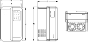
HV580L series inverter structure shape dimension and installation dimension sketch
| VFD type | Mounting position mm | External dimension
mm |
Mounting position diameter mm | Weight
Kg |
|||
| A | B | H | W | D | |||
| HV580L-004G3 | 148 | 236 | 248 | 150 | 183 | ф5.0 | 3.1 |
| HV580L-5R5G3 | |||||||
| HV580L-7R5G3 | |||||||
| HV580L-011G3 | 190 | 305 | 322 | 208 | 192 | Ф6.0 | 5.9 |
| HV580L-015G3 | |||||||
| HV580L-018G3 | 235 | 447 | 437 | 286 | 220 | Ф7.0 | 17 |


