Description
Overview:
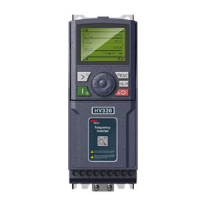
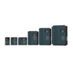
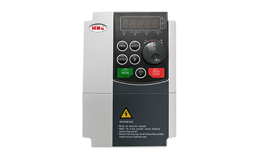
New HV610 series is a general current vector control inverter integrated with the performance and features in a high degree. HV610 with industry-leading drive performance and functionality control, using unique current vector control algorithm can efficiently drive induction motor to achieve high accuracy, high torque and high-performance control.
Detachable keyboard,support copy parameters by keypad, debugging software on PC, built-in EMC filter, reduce EMC interference, ,ect. These optimized designs make HV610 series an industry-leading product and bring tangible benefits to customers.
Customer success, Market Service!HV610 in terms of performance and control are worthy of trust!
Features:
1. Advanced motor control technology support Open loop vector control(SVC), Closed loop vector control(FVC) and V/F control.
2. Different input voltage(220V single phase/220V 3 phase/380V 3 phase/460V 3 phase).
3. High starting torque characteristics and precise speed control.
4. Rich and flexible I/O accesses and field bus options.
5. Suitable for all regions which have different grid and voltage.
6. Upgrade I/O(NPN/PNP compatible) can meet more application requirement without controller(PLC)
7. Programmable DI/DO/AI/AO, and Modbus RTU make easy communication with other devices.
8. Detachable keyboard,support copy parameters by keypad, support keyboard extension.
9. Debugging software, suitable for parameter set, waveform monitor, optimizing device performance.
10. Kinds of PG cardse, match kinds of encoder type for high performance closed vector loop control.
11. Multi-pumps control, constant pressure water supply function.
12. Built-in EMC filter, reduce EMC interference , reduce malfunctions and improve accuracy.
13. Kinds of communication cards are available, Easy to integrate into the network to help Industry 4.0.
Parameters:
Model Definition:
|
Model |
Power supply capacity (KVA) |
Input current (A) |
Output current (A) |
Adaptive motor (KW) (HP) |
|
|
G1 input voltage range: Single-phase AC220V±15%, 50 / 60 Hz |
|||||
|
HV610-R75G1 |
3.0 |
11.0 |
4.0 |
0.75 |
1 |
|
HV610-1R5G1 |
4.8 |
18.0 |
7.0 |
1.5 |
2 |
|
HV610-2R2G1 |
7.1 |
27.0 |
9.6 |
2.2 |
3 |
|
G2 input voltage range: Three-phase AC220V±15%, 50 / 60 Hz |
|||||
|
HV610-R75G2 |
3 |
5 |
3.8 |
0.75 |
1 |
|
HV610-1R5G2 |
4.0 |
5.8 |
5.1 |
1.5 |
2 |
|
HV610-2R2G2 |
5.9 |
10.5 |
9.0 |
2.2 |
3 |
|
HV610-004G2 |
8.9 |
14.6 |
13.0 |
3.7 |
5 |
|
HV610-5R5G2 |
17 |
26.0 |
25.0 |
5.5 |
7.5 |
|
HV610-7R5G2 |
21 |
35.0 |
32.0 |
7.5 |
10 |
|
HV610-011G2 |
30 |
46.5 |
45 |
11 |
15 |
|
HV610-015G2 |
40 |
62 |
60 |
15 |
20 |
|
HV610-018G2 |
57 |
76 |
75 |
18 |
25 |
|
HV610-022G2 |
69 |
92 |
91 |
22 |
30 |
|
HV610-030G2 |
85 |
113 |
112 |
30 |
40 |
|
HV610-037G2 |
114 |
157 |
150 |
37 |
50 |
|
HV610-045G2 |
134 |
180 |
176 |
45 |
60 |
|
HV610-055G2 |
160 |
214 |
210 |
55 |
75 |
|
HV610-075G2 |
231 |
307 |
304 |
75 |
100 |
|
HV610-093G2 |
250 |
385 |
377 |
90 |
125 |
|
HV610-110G2 |
280 |
430 |
426 |
110 |
150 |
|
HV610-132G2 |
396 |
525 |
520 |
132 |
175 |
|
HV610-160G2 |
500 |
665 |
650 |
160 |
220 |
|
HV610-185G2 |
560 |
735 |
725 |
185 |
245 |
|
HV610-200G2 |
630 |
835 |
820 |
200 |
270 |
|
HV610-220G2 |
700 |
925 |
910 |
220 |
300 |
|
G3 input voltage range: Three-phase AC 380~440 (-15%~+10%), 50 / 60 Hz |
|||||
|
HV610-R75G3 |
1.5 |
3.4 |
2.1 |
0.75 |
1 |
|
HV610-1R5G3 |
3.0 |
5.0 |
3.8 |
1.5 |
2 |
|
HV610-2R2G3 |
4.0 |
5.8 |
5.1 |
2.2 |
3 |
|
HV610-004G3 |
5.9 |
10.5 |
9.0 |
4.0 |
5 |
|
HV610-5R5G3 |
8.9 |
14.6 |
13.0 |
5.5 |
7.5 |
|
HV610-7R5G3 |
11 |
20.5 |
17.0 |
7.5 |
10 |
|
HV610-011G3 |
17 |
26.0 |
25.0 |
11 |
15 |
|
HV610-015G3 |
21 |
35.0 |
32.0 |
15 |
20 |
|
HV610-018G3 |
45 |
42 |
37 |
18.5 |
25 |
|
HV610-022G3 |
54 |
50 |
45 |
22 |
30 |
|
HV610-030G3 |
60 |
68 |
60 |
30 |
40 |
|
HV610-037G3 |
63 |
83 |
75 |
37 |
50 |
|
HV610-045G3 |
81 |
102 |
91 |
45 |
60 |
|
HV610-055G3 |
97 |
124 |
112 |
55 |
75 |
|
HV610-075G3 |
127 |
169 |
150 |
75 |
100 |
|
HV610-093G3 |
150 |
203 |
176 |
90 |
125 |
|
HV610-110G3 |
179 |
248 |
210 |
110 |
150 |
|
HV610-132G3 |
192 |
256 |
253 |
132 |
175 |
|
HV610-160G3 |
231 |
307 |
304 |
160 |
220 |
|
HV610-185G3 |
242 |
350 |
340 |
185 |
245 |
|
HV610-200G3 |
250 |
385 |
377 |
200 |
270 |
|
HV610-220G3 |
280 |
430 |
426 |
220 |
300 |
|
HV610-250G3 |
355 |
468 |
465 |
250 |
340 |
|
HV610-280G3 |
396 |
525 |
520 |
280 |
380 |
|
HV610-315G3 |
445 |
590 |
585 |
315 |
430 |
|
HV610-355G3 |
500 |
665 |
650 |
355 |
420 |
|
HV610-400G3 |
565 |
785 |
725 |
400 |
530 |
|
HV610-450G3 |
630 |
883 |
820 |
450 |
600 |
|
HV610-500G3 |
720 |
954 |
920 |
500 |
670 |
|
HV610-560G3 |
780 |
1085 |
1030 |
560 |
750 |
|
HV610-630G3 |
800 |
1184 |
1100 |
630 |
840 |
|
G4 input voltage range: Three-phase AC 460~480 (-15%~+10%), 50 / 60 Hz |
|||||
|
HV610-R75G4 |
1.5 |
3.4 |
2.1 |
0.75 |
1 |
|
HV610-1R5G4 |
3.0 |
5.0 |
3.8 |
1.5 |
2 |
|
HV610-2R2G4 |
4.0 |
5.8 |
5.1 |
2.2 |
3 |
|
HV610-004G4 |
5.9 |
10.5 |
9.0 |
4.0 |
5 |
|
HV610-5R5G4 |
8.9 |
14.6 |
13.0 |
5.5 |
7.5 |
|
HV610-7R5G4 |
11 |
20.5 |
17.0 |
7.5 |
10 |
|
HV610-011G4 |
17 |
26.0 |
25.0 |
11 |
15 |
|
HV610-015G4 |
21 |
35.0 |
32.0 |
15 |
20 |
|
HV610-018G4 |
45 |
42 |
37 |
18.5 |
25 |
|
HV610-022G4 |
54 |
50 |
45 |
22 |
30 |
|
HV610-030G4 |
60 |
68 |
60 |
30 |
40 |
|
HV610-037G4 |
63 |
83 |
75 |
37 |
50 |
|
HV610-045G4 |
81 |
102 |
91 |
45 |
60 |
|
HV610-055G4 |
97 |
124 |
112 |
55 |
75 |
|
HV610-075G4 |
127 |
169 |
150 |
75 |
100 |
|
HV610-093G4 |
150 |
203 |
176 |
90 |
125 |
|
HV610-110G4 |
179 |
248 |
210 |
110 |
150 |
|
HV610-132G4 |
192 |
256 |
253 |
132 |
175 |
|
HV610-160G4 |
231 |
307 |
304 |
160 |
220 |
|
HV610-185G4 |
242 |
350 |
340 |
185 |
245 |
|
HV610-200G4 |
250 |
385 |
377 |
200 |
270 |
|
HV610-220G4 |
280 |
430 |
426 |
220 |
300 |
|
HV610-250G4 |
355 |
468 |
465 |
250 |
340 |
|
HV610-280G4 |
396 |
525 |
520 |
280 |
380 |
|
HV610-315G4 |
445 |
590 |
585 |
315 |
430 |
|
HV610-355G4 |
500 |
665 |
650 |
355 |
420 |
|
HV610-400G4 |
565 |
785 |
725 |
400 |
530 |
|
HV610-450G4 |
630 |
883 |
820 |
450 |
600 |
|
HV610-500G4 |
720 |
954 |
920 |
500 |
670 |
|
HV610-560G4 |
780 |
1085 |
1030 |
560 |
750 |
|
HV610-630G4 |
800 |
1184 |
1100 |
630 |
840 |
Standard specification:
|
Item |
Specifications |
||
|
Basic Functionalist |
Highest frequency | Vector control: 0 ~ 500 Hz V/F control: 0:3200Hz | |
| Carrier frequency | 0.5kHz~16kHz
The carrier frequency can be automatically adjusted according to the load characteristics. |
||
| Input frequency resolution | Digital setting: 0.01 Hz
Analog setting: highest frequency * 0.025 % |
||
| Control mode |
1: Open loop vector control 2: Closed loop vector control 3: V/F control
|
||
| Start torque | G type: 0.5 Hz / 150 %
P type: 0.5 Hz / 100 % |
||
| Speed control range | 1:100 | ||
| Speed stabilization accuracy | ±0.5% | ||
| Torque control accuracy | ±5% | ||
| Overload capacity | Model G machine:
150 % rated current 60s; 180 % rated current 3s. |
||
| Torque increase | Automatic torque increase;
The manual torque is increased by 0.1 % – 30.0 % |
||
| V/F curve | Three ways: linear; Multipoint type; N – power V/F curve ( power 1.2, power 1.4, power 1.6, power 1.8, power 2 ) | ||
| V/F separation | Two methods: full separation and half separation | ||
| Acceleration and deceleration curve | Straight line or S curve acceleration and deceleration mode. | ||
| Four kinds of acceleration and deceleration times, | |||
| The acceleration and deceleration time range is 0.0 to 6500.0 S. | |||
| DC brake | DC braking frequency: 0.00 Hz ~ maximum frequency | ||
| Braking time: 0.0s ~ 36.0s | |||
| Brake action current value: 0.0 % – 100.0 % | |||
| inching | Inching frequency range: 0.00 Hz ~ 50.00 Hz. Inching acceleration and deceleration time 0.0s ~ 6500.0 s. | ||
| Simple PLC, multi-stage speed operation | Up to 16 – speed operation via built-in PLC or control terminal | ||
| Built – in PID | Closed-loop control system capable of conveniently realize process control | ||
| Automatic voltage regulation ( AVR ) | When the grid voltage changes, the output voltage can be automatically kept constant. | ||
| over voltage and over-loss rate control | Automatically limit the current and voltage during operation to prevent frequent over current and over voltage trips. | ||
| Fast current limiting function | Minimize over-current faults and protect the normal operation of the frequency inverter | ||
| Torque limitation and control | The ” excavator” feature automatically limits the torque during operation to prevent frequent over current trips; Open loop vector mode can realize torque control | ||
|
Individualized performance |
Outstanding performance | Using high performance current vector control technology to realize asynchronous motor control | |
| Stop at once | When the instantaneous power failure occurs, the load feedback energy compensates for the voltage drop and the frequency inverter will continue to operate for a short period of time. | ||
| Fast current limiting | Avoiding frequent over current faults of the frequency inverter | ||
| Timing control | Timing control function: set the time range from 0.0 min to 6500.0 min | ||
| Switch between two motors | Two sets of motor parameters can realize switching control of two motors | ||
| Bus support | Supports a variety of Fieldbus: RS – 485,PROFIBUS | ||
|
Running |
Command source | Operation panel setting, control terminal setting, serial communication port setting. Can be switched in various ways | |
| frequency source | Multiple frequency sources: digital setting, analog voltage setting, analog current setting, pulse setting, serial port setting. Can be switched in various ways | ||
| Auxiliary frequency source | Various auxiliary frequency sources. Can flexibly realize auxiliary frequency fine tuning and frequency synthesis | ||
| Input terminal | Standard 7 digital input terminals, of which 1 supports high-speed pulse input of up to 100 khz; Three analog input terminals, one supporting only 0 ~ 10v voltage input, one supporting 0 ~ 10v voltage input or 4 ~20mA current input,
1 analog input terminal, supporting – 10 ~ 10v voltage input |
||
| Output terminals | 1 high-speed pulse output terminal ( optional open collector type ), supporting square wave signal output of 0 ~ 100 khz
1 digital output terminal 1 relay output terminal 2 analog output terminals to support 0 ~ 20ma current output or 0 ~10v voltage output |
||
|
Environment |
Place of use | Dust – free, metal dust, corrosive gases, flammable gases, oil fog, salt fog, water vapor, dripping direct sunlight – free indoor | |
| Altitude | Below 1,000 meters | ||
| Ambient temperature | -10℃~40℃ | ||
| Humidity | Less than 90 % RH without condensation | ||
| Vibration | Less than 0.5g. | ||
| Storage temperature | -25℃~65℃ | ||
| Protection grade | IP20 | ||
Dimension:
Product Outline, Mounting Dimension, and Weight:
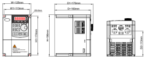
Fig 1(R75G3-2R2G3)
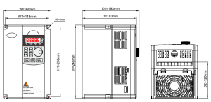
Fig 2(004G3-7R5G3)
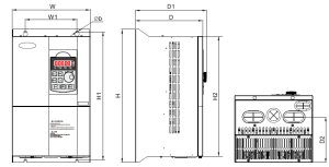
Fig 3(011G3-200G3)
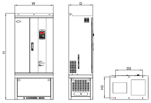
Fig 4(185G3-560G3)
| Model | External dimension
( mm ) |
Installation hole location
( mm ) |
Mounting aperture
( mm ) |
Figure | ||||||
| W | H | D | W1 | H1 | D1 | H2 | D2 | d | ||
| Single-phase G1 AC220 V | ||||||||||
| HV610-R75G1 | 101 | 152 | 117 | 89 | 140 | 128 | 84 | 5 | 1 | |
| HV610-1R5G1 | ||||||||||
| HV610-2R2G1 | 125 | 220 | 166 | 110 | 205 | 177 | 124 | 6.5 | 1 | |
| Three-phase G2 AC220 V | ||||||||||
| HV610-R75G2 | 125 | 186 | 160 | 113 | 174 | 170 | / | 113 | 5 | 1 |
| HV610-1R5G2 | ||||||||||
| HV610-2R2G2 | 160 | 248 | 183 | 148 | 236 | 193 | / | 128 | 5 | 2 |
| HV610-004G2 | ||||||||||
| HV610-5R5G2 | 195 | 330 | 185 | 150 | 315 | 197 | 284 | 130 | 6 | 3 |
| HV610-7R5G2 | ||||||||||
| HV610-011G2 | 227 | 388 | 196 | 150 | 375 | 206 | 350 | 133 | 7 | 3 |
| HV610-015G2 | 255 | 435 | 202 | 150 | 425 | 213 | 400 | 140 | 7 | 3 |
| HV610-018G2 | ||||||||||
| HV610-022G2 | 307 | 557 | 266 | 230 | 537 | 278 | 501 | 204 | 9 | 3 |
| HV610-030G2 | ||||||||||
| HV610-037G2 | 377 | 628 | 280 | 240 | 600 | 292 | 568 | 228 | 9 | 3 |
| HV610-045G2 | ||||||||||
| HV610-055G2 | ||||||||||
| HV610-075G2 | 500 | 788 | 350 | 270 | 762 | 357 | 728 | 266 | 13 | 3 |
| HV610-093G2 | 540 | 900 | 348 | 320 | 867 | 358 | 828 | 278 | 13 | 3 |
| HV610-110G2 | ||||||||||
| HV610-132G2 | 620 | 1035 | 390 | 500 | 1005 | 400 | 960 | 307 | 13 | 3 |
| HV610-160G2 | 780 | 1290 | 400 | 600 | 1257 | 410 | 1203 | 316 | 13 | 3 |
| HV610-185G2 | ||||||||||
| HV610-200G2 | ||||||||||
| HV610-220G2 | ||||||||||
| Three-phase G3 AC380 V | ||||||||||
| HV610-R75G3 | 125 | 186 | 160 | 113 | 174 | 170 | / | 113 | 5 | 1 |
| HV610-1R5G3 | ||||||||||
| HV610-2R2G3 | ||||||||||
| HV610-004G3 | 160 | 248 | 183 | 148 | 236 | 193 | / | 128 | 5 | 2 |
| HV610-5R5G3 | ||||||||||
| HV610-7R5G3 | ||||||||||
| HV610-011G3 | 195 | 330 | 185 | 150 | 315 | 197 | 284 | 130 | 6 | 3 |
| HV610-015G3 | ||||||||||
| HV610-018G3 | 227 | 388 | 196 | 150 | 375 | 206 | 350 | 133 | 7 | 3 |
| HV610-022G3 | ||||||||||
| HV610-030G3 | 255 | 435 | 202 | 150 | 425 | 213 | 400 | 140 | 7 | 3 |
| HV610-037G3 | ||||||||||
| HV610-045G3 | 307 | 557 | 266 | 230 | 537 | 278 | 501 | 204 | 9 | 3 |
| HV610-055G3 | ||||||||||
| HV610-075G3 | 377 | 628 | 280 | 240 | 600 | 292 | 568 | 228 | 9 | 3 |
| HV610-093G3 | ||||||||||
| HV610-110G3 | ||||||||||
| HV610-132G3 | 500 | 788 | 350 | 270 | 762 | 357 | 728 | 266 | 13 | 3 |
| HV610-160G3 | ||||||||||
| HV610-185G3 | 540 | 900 | 348 | 320 | 867 | 358 | 828 | 278 | 13 | 3 |
| HV610-200G3 | Cabinet machine (H x W x D): 11268x540x358 (H3=266mm D3=440mm) | 4 | ||||||||
| HV610-220G3 | ||||||||||
| HV610-250G3 | 620 | 1035 | 390 | 500 | 1005 | 400 | 960 | 307 | 13 | 3 |
| HV610-280G3 | Cabinet machine (H x W x D): 1400x620x400 (H3=340mm D3=440mm) | 4 | ||||||||
| HV610-315G3 | 780 | 1290 | 400 | 600 | 1257 | 410 | 1203 | 316 | 13 | 3 |
| HV610-355G3 | Cabinet machine (H x W x D): 1650x780x410 (H3=340mm D3=600mm) | 4 | ||||||||
| HV610-400G3 | ||||||||||
| HV610-450G3 | Cabinet machine (H x W x D): 1750x950x460 (H3=320mm D3=820mm) | 4 | ||||||||
| HV610-500G3 | ||||||||||
| HV610-560G3 | ||||||||||
| HV610-630G3 | ||||||||||
| Three-phase G4 480 V | ||||||||||
| HV610-R75G4 | 125 | 186 | 160 | 113 | 174 | 170 | / | 113 | 5 | 1 |
| HV610-1R5G4 | ||||||||||
| HV610-2R2G4 | ||||||||||
| HV610-004G4 | 160 | 248 | 183 | 148 | 236 | 193 | / | 128 | 5 | 2 |
| HV610-5R5G4 | ||||||||||
| HV610-7R5G4 | ||||||||||
| HV610-011G4 | 195 | 330 | 185 | 150 | 315 | 197 | 284 | 130 | 6 | 3 |
| HV610-015G4 | ||||||||||
| HV610-018G4 | 227 | 388 | 196 | 150 | 375 | 206 | 350 | 133 | 7 | 3 |
| HV610-022G4 | ||||||||||
| HV610-030G4 | 255 | 435 | 202 | 150 | 425 | 213 | 400 | 140 | 7 | 3 |
| HV610-037G4 | ||||||||||
| HV610-045G4 | 307 | 557 | 266 | 230 | 537 | 278 | 501 | 204 | 9 | 3 |
| HV610-055G4 | ||||||||||
| HV610-075G4 | 377 | 628 | 280 | 240 | 600 | 292 | 568 | 228 | 9 | 3 |
| HV610-093G4 | ||||||||||
| HV610-110G4 | ||||||||||
| HV610-132G4 | 500 | 788 | 350 | 270 | 762 | 357 | 728 | 266 | 13 | 3 |
| HV610-160G4 | ||||||||||
| HV610-185G4 | 540 | 900 | 348 | 320 | 867 | 358 | 828 | 278 | 13 | 3 |
| HV610-200G4 | Cabinet machine (H x W x D): 11268x540x358 (H3=266mm D3=440mm) | 4 | ||||||||
| HV610-220G4 | ||||||||||
| HV610-250G4 | 620 | 1035 | 390 | 500 | 1005 | 400 | 960 | 307 | 13 | 3 |
| HV610-280G4 | Cabinet machine (H x W x D): 1400x620x400 (H3=340mm D3=440mm) | 4 | ||||||||
| HV610-315G4 | 780 | 1290 | 400 | 600 | 1257 | 410 | 1203 | 316 | 13 | 3 |
| HV610-355G4 | Cabinet machine (H x W x D): 1650x780x410 (H3=340mm D3=600mm) | 4 | ||||||||
| HV610-400G4 | ||||||||||
| HV610-450G4 | Cabinet machine (H x W x D): 1750x950x460 (H3=320mm D3=820mm) | 4 | ||||||||
| HV610-500G4 | ||||||||||
| HV610-560G4 | ||||||||||
| HV610-630G4 | ||||||||||
Download:
| Series | Model | Download |
| Frequency Inverter | HV610_MONITOR -EN | |
| Frequency Inverter | HV610 Series Inverter Catalog-2020 | |
| Frequency Inverter | HV610-DP card instruction_202003 | |
| Frequency Inverter | HV610 PG card instruction_202003 | |
| Frequency Inverter | HV610 English User Manual -V0.2_20210605 |